[DOC] BLTouch wiring for Mega S/P #210
Comments
|
Hi Stefan, Good catch and info. regards Poul |
|
You have to redefine the The current value is 2. The one to swap with should be the Don’t know why, but I initially had "FAN 1" Pin (7) in mind… I did not verify this! |
|
This issue is stale because it has been open 30 days with no activity. Remove stale label / comment or this will be closed in 5 days. |
|
Somehow I missed this ticket. Sorry. The question is whether the PCB always looks like this on the Mega Pro, or whether Mega S PCBs are also installed. If it always looks like yours, I would add the pin change for the Mega Pro into the source code and adapt the documentation. May I use your picture for this? :) |
|
I received two feedbacks of people with Mega P and the very same Hotend PCB. Feel free to use the pictures. A second change: Both boards work well with the MEGA_P_BLT_10 target.
|


|
The documentation is updated and I put your name in it if this is ok? Thank you very much! Both other Trigorilla-Boards are already covered in the Beginner's Guide or Einsteiger Leitfaden. Maybe I should reference the one guide in the other ;) |
My name's already here, so again, feel free to use it.
Second link in the README and I obviously missed that one, nevermind 🙈 Difference was probably too obvious. |
|
Dear Knutwurst, I own a I3 Mega Pro. With Board v.0.0.2. am I right, if I will use H1 and H2 —> I have to change the wires from A5 to B5 and B5 to A5? (zwei Lösungen dokumentiert um den BL Touch Sensor elegant am MEGA Pro anzuschließen. Hierbei kann der freie "X-Stop" Anschluss verwendet werden, wenn man entweder im oberen grünen Stecker die zwei Leitungen A5 und B5 wechselt) |
I comfirm this change is wrong.MEGA PRO must swap A5 and B5 |
|
Hi @stklcode, You state in your first post:
Can you please provide an explanation to this, why it’s not suitable? |
|
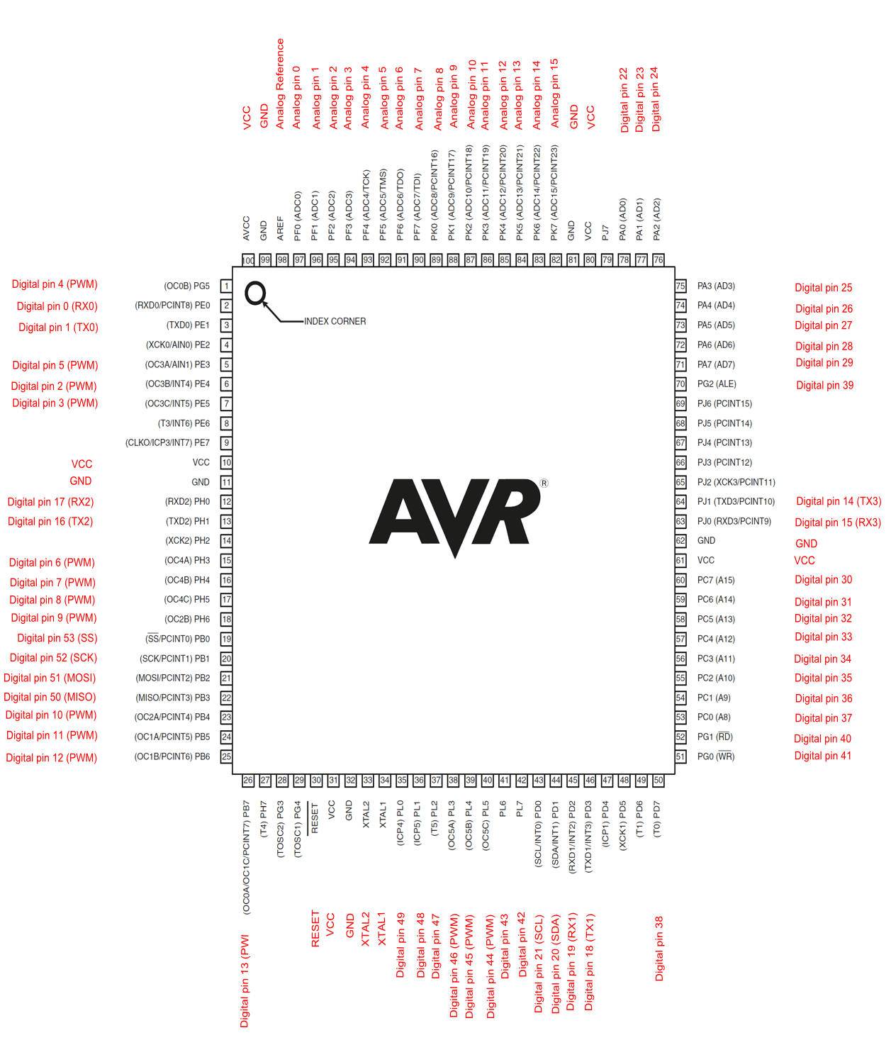
See the pinout picture above. The “switch“ port uses shared pins with The T0 header. It simply provides power for the piezo buzzer that is shipped with the Mega P, so no usable signal is actually routed to the printer that can be switch via firmware. Of course it is theoretically possible to use the pins. One might cut the lanes to A/B7 on the PCB and solder a wire to B5. Piezo leveling is obviously lost then. I would rather cut both lanes and rewire it to the hortend pins to connect the laser module. |
|
Ah, I see. Appreciate your explanation. Your original solution is much easier and less harmful to the PCB. :) Thanks! |
|
Hi, me again. I know what to do to make it work now. So far, so good. But I’m lacking some comprehension. I understood, we need B5. And according this thread and RAMPS.h, B5 maps to pin 2 apparently. Sorry, if this is getting to off-topic, but I’m eager to also understand the backgrounds. :) |
|
You can follow the wire and see/measure where it ends. For the 0.0.2 board (Trigorilla 1.4 clone) this is the “X+“ header of the endstops block in the southeast corner. There are a few pinout diagrams around the web where you will see it is pin D2. Otherwise you might look further and follow the connection from the pinheaded to the AtMega. The i3 Mega has only one X endstop that is positioned on the frame, so the second pin is unused. A5 and B5 are intended for alternative X limit switches on the hotend assembly. There are several hotend PCBs around, ours has connections on A5. This one is either not connected on the other end or shared with the actual limit switch, so it cannot trivially be swapped in the firmware. |
|
Thanks! Yeah, I found a few pinout diagrams, but was confused with different boards and thus different layouts. In addition, I wasn’t sure if „D2“ equals pin 2. Thanks for confirmation! So B5 is actually an extension of D2 to the hotend PCB? If yes to all, we could easily use one of these https://www.3djake.de/antclabs/bltouch-verlaengerungskabel-sm-du, swap only red and brown for the servo and that’s it. No soldering, no swapping cables on the PCB connector, no changing the firmware. Right? :) |
|
That’s correct. You can directly connect 5 long wires (2x GND, +5V, Servo 1, D2) on the Trigorilla board. E.g. rd/ye/bn to the 3pin servo header (as usual) and bk/wh to the endstops block. on the 0.0.2 the wiring would be:
|
|
I agree to the wiring. Thanks! After opening my Pro, I found that the endstop pins are already occupied by the SD-TFT-Hub-Switch PCB. I think, I understand the complexity behind this now. :) Appreciate all your help and explanations! |
|
Appreciate this as well. I have the Mega Pro. I was able to get this setup and working. Sadly yes you can't wire the BL touch onto the board as just like mnggh said, the PCB for it has a daughter board that covers and uses all the pins. However simply taking the wires for A5 / B5 I used a little needle to release the wires from the harness and swapped them. Just a note, if you plan to run the wire for the servo through the wire bundle, the 1m extension cable is not long enough. Thankfully my buddy had a 1m extra he didn't need on hand, so I just took it and modified it to be an extender with the wire connectors that came with it extra. |
|
Hi Kilandor, For connecting the BLtouch to the mainboard, there seems to be way. I was inspired by this video, in which the creator uses pin 21 on the board. Afterwards he reconfigured and compiled the firmware using the new pin 21 for Z_MIN_PROBE_PIN. HTH. |
|
Hey Everyone! I did run the probe configration as recommended in (https://github.com/knutwurst/Marlin-2-0-x-Anycubic-i3-MEGA-S/wiki/BLTouch-Installation-(deutsch)) and could also see that the probe is triggered (M114 in Pronterface) Firmware: MEGA_S_DGUS_TMC_BLT_10_v1.4.1 so - as i assume - the wireing and firmware is correct. |
|
Nevermind - i just rerun the autolevel special menu thingy and it works now... |
|
Sorry for asking here, because I'm trying to do this with Klipper but this is one of the only Informations I could find for the Mega Pro. I got my 3D Touch wired and the Servo Pins are working. According to Information provided it should now point to D3 (Port E5), thats already used for the X-Endstop in Klipper so it wont work. I then swapped the Pins on the Green connector, where I'm not sure if i swapped the right ones at all. I'm probably just using the wrong Port for my config. I refered to this Pinlayout https://cdn.thingiverse.com/assets/b5/c5/55/77/ba/TriGoRiLLa_PINs.pdf If someone could help me, I would really appreciate that. Thanks! |
|
I'm currently having issues with installing a BLTouch (Clone from Geeetech) into my printer with Klipper (I know this is not the Klipper repo, but maybe someone has an idea)
But when I try to query the sensor_pin to ^PE4 (which should be Digital PIN 2) I only get 'open' state back.
EDIT: My config (in case someone can use this): Thanks in advance |
|
This issue has been automatically locked since there has not been any recent activity after it was closed. Please open a new issue for related bugs. |
I recently added a BLTouch sensor so my Mega P. The Mega P and - according to the PCB print - also the Mega S share a different hotend PCB which makes it even more elegant to add the sensor. There is an additional pinheader labelled "SWITCH" which is used for the piezo leveling helper. This is not suitable.
But the PCB features an "X-STOP" labelled slot for another pinheader. It's 2mm spacing, but with little bending a 2.54mm pinheader fits perfectly, if you want to change the original BLTouch cable.
This header is connected to A5 and A6/B6. The Pin we need is B5.
B5 is not connected on this PCB, so it's safe to swap A5 and B5 in the green connector. Doing so you can use the Knutwurst as is. Otherwise you would have to change the pin in the firmware configuration.
Works perfectly without any change to this FW.
The text was updated successfully, but these errors were encountered: